8
Installation
1. Decide the best location for the cables to enter the
vehicle, and the location of the power switch and
receiver (see “Installing the switch and receiver”on
pages 9 and 10). Drill a 1/2” hole in the roof, push
wires inside. Make proper connections.
Youmusthaveltered+12VDCpowersource.
2. If installing a second receiver, route second coax
cable (not supplied) through empty Heyco into base.
Connect to secondary coax connection point. See
page 6.
3. Place cable-entry plate over hole and cables. Screw
in place. Seal plate and screw holes with approved
sealant (not included).
4. Depending on the length of the cable on the roof,
you may need to use cable clamps or wire ties (not
provided) between the unit and your cable-entry plate.
Clamping the cable every 12”-16” should eliminate any
unnecessary cable movement.
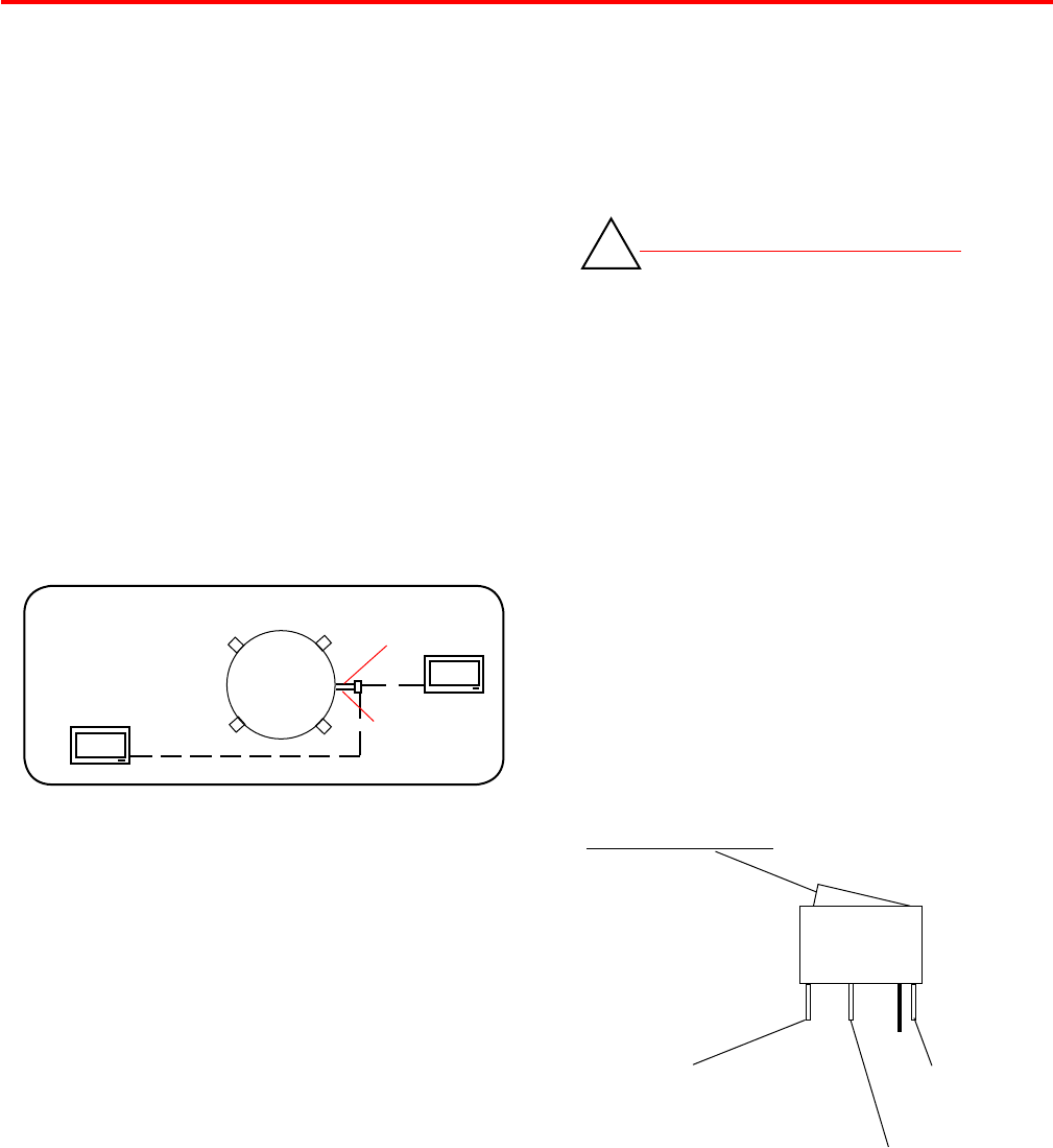
Cable entry installation —
REV. 7/07
PRIMARY
RECEIVER
(GRAY WIRE)
Mv-3500
roADTriP
SECONDARY
RECEIVER
(WHITE WIRE-
OEM ONLY)
COAX CABLE ROUTING
INSTALLING THE POWER SWITCH
1. Choose a location to install the Movin’ View power
ON/OFF switch. Remember when selecting a location
that you will need to run the +12VDC power cable from
the Movin’ View antenna to the switch. Be sure the
switch is in the OFF position before continuing.
See Figure 7 page 8.
Wall or panel mount: Drill 1-1/4” hole, pull wires
through wall or panel.
2. Connect the ground wire from the vehicle and the
BLACK ground wire from the antenna together,
using large yellow ag connector.
3. Connect the YELLOW ag connector to
the silver spade on the switch.
4. Connect the RED wire from the antenna to the
small RED ag connector.
5. Connect small RED ag connector to center
spade on switch.
6. Connect the +12 V power wire from the vehicle to
a small RED ag connector.
7. Connect small RED ag connect to isolated
spade on switch.
INSTALLING THE POWER SWITCH DIAGRAM
STEPS 2 & 3
TWO GROUND WIRES
1 FROM VEHICLE
1 BLACK WIRE FROM
SATELLITE DISH
STEPS 4 & 5
RED POWER
WIRE FROM
DISH
STEPS 6 &7
+12 V FROM VEHICLE
ON/OFF ROCKER SWITCH
WITH LIGHT
(Shown in OFF position.)
FIGURE 7
DO NOT CUT DATA CABLE SHORT!
!
HD Ready
The power wire is bundled with a data cable for con-
necion to the Winegard HD Satellite Interface. DO NOT
CUT DATA CABLE SHORT! If you will not connect the
HD Satellite Interface at this time, hide the data cable
behind the wall plate for future use.
MOVIN’ VIEW
(NOT
SUPPLIED)
 (4 pages)
 (24 pages)
 Manymanuals.com
 Manymanuals.de
 Manymanuals.fr
 Manymanuals.it
 Manymanuals.pl
 Manymanuals.cz
 Manymanuals.es
 Manymanuals-pt.com
Commentaires sur ces manuels